
ZCC2000 Printing Operation
- Power on - Press the circular start button in the lower right corner of the front of the device. (Fig P-23)
- Adjust the printing platform
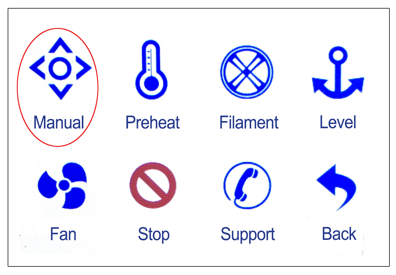
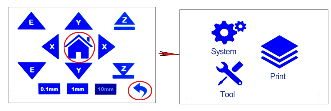
- Click on the [Tools]-[Manual] icon in the control panel. (Fig. P-24)
- Click on the [House] icon to bring the printing platform back to its origin. (Fig. P-25)
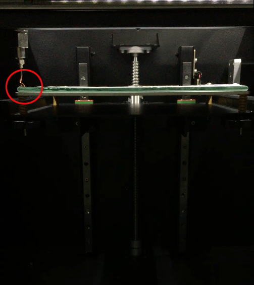
- After the platform returns to its original position, place the processed glass inside. (Fig. P-26)
-
* Due to bumps during transportation, the platform may experience displacement, causing it to be too close to the nozzle after returning to its original position, resulting in the inability to place the glass. If this situation occurs, please adjust the platform in the following way:
- Rotate the leveling nut below the platform counterclockwise to lower the platform (Fig. P-26)
- Four leveling nuts need to be adjusted to lower the platform position, so that the glass can be inserted.
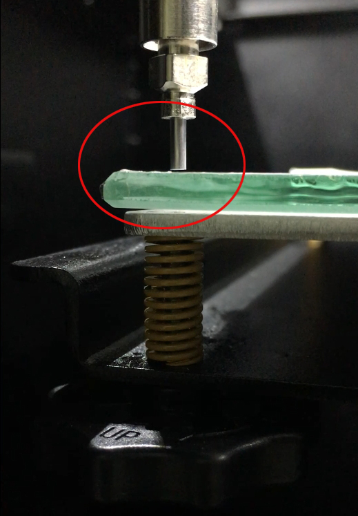
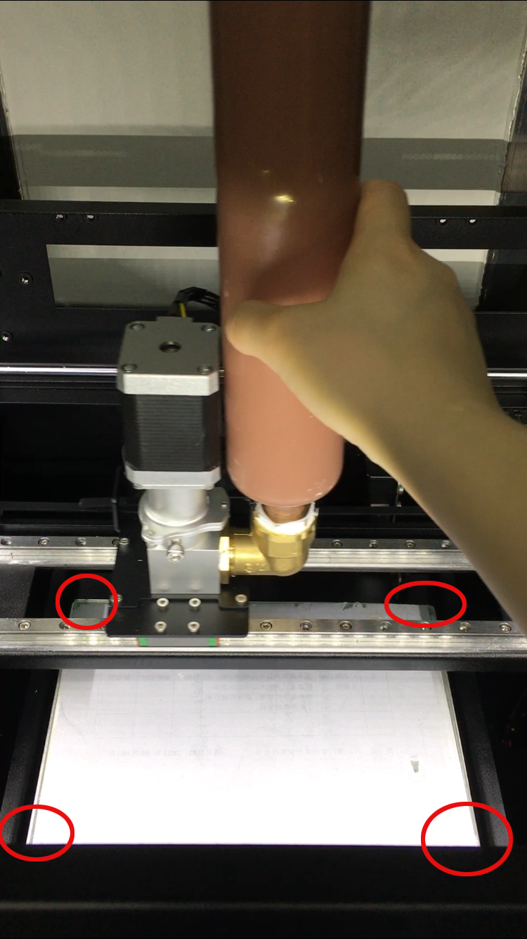
- Fine tune the distance between the glass and the nozzle. (Fig. P-27)
- After inserting the glass, use the leveling nut (Fig. P-26) under the platform to adjust the distance between the nozzle and the glass.
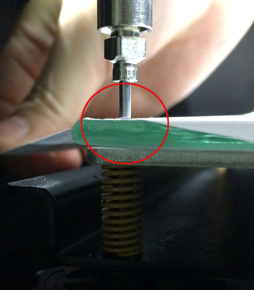
- It is recommended to reserve a distance of about 1-2 A4 paper thicknesses. (Fig. P-28)
- After completion, click on the [Back] icon in the bottom right corner of the control panel, and then click on the [Stop] icon. (Fig. P-29)
- After clicking the [Emergency Stop] icon, follow the adjustment method in steps a and b above to manually push the extruder to the other three corners of the glass and adjust the distance between the glass and the nozzle in sequence. (Fig. P-30)
- Check the mud discharge of the extruder.
- Increase air pressure - pull down the pressure regulating valve knob until the orange part is exposed. (Fig. P-31)
- Then rotate counterclockwise to increase air pressure (clockwise – decrease pressure), with a general adjustment range of 0.45-0.6MPa. (Fig. P-31)
- Click the [Manual] icon in the control panel. (Fig. P-32)
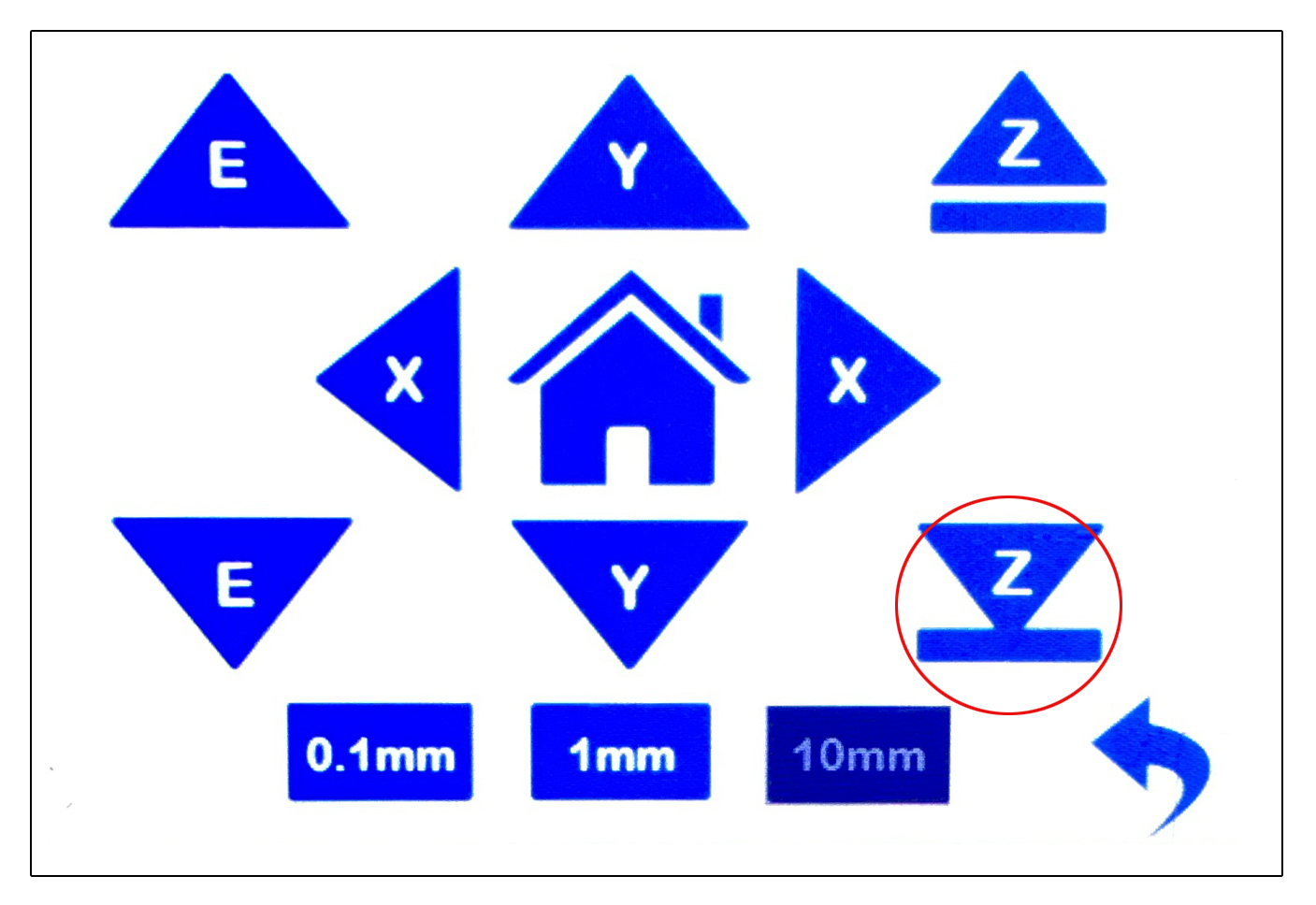
- Then click on the downward [Z] icon to lower the platform to a certain height for easy observation of the mud situation. (Fig. P-33)
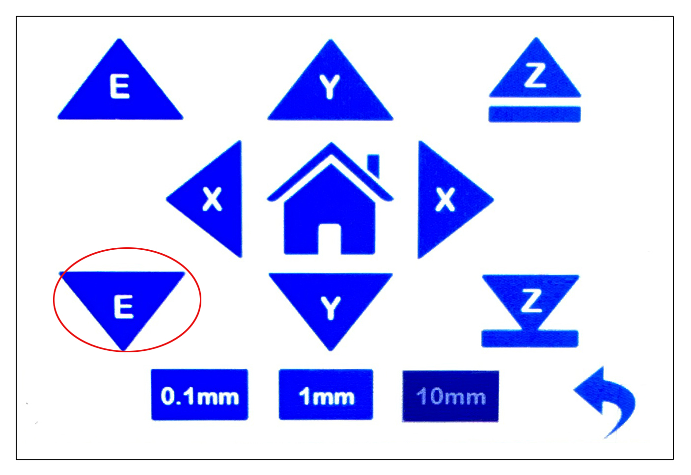
- After the platform descends, click on the downward [E] icon (Fig. P-34) in the control panel. If it is the first time to use it, click a few more times to observe whether the nozzle emits mud smoothly. (P-35)
- There is no problem with mud discharge. After removing the excluded mud click on the [House] icon in the control panel to return the platform to its original position, and then continue to click on the [Back] icon to return to the main interface. (P-36)
-
* In case of inability to squeeze out mud or low mud output:
- Attempt to increase air pressure (adjustment range not exceeding 0.6MPa);
- Check if each air pipe connection is properly inserted to avoid air leakage;
- Check if there are any foreign objects blocking the inside of the extruder;
- Check if the mud used is too dry and replace it with a harder mud.
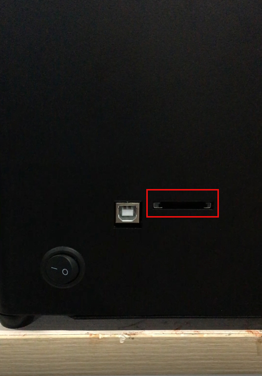
- Insert and remove the SD card.
- The card slot is located below the right side of the machine. (Fig. P-37)
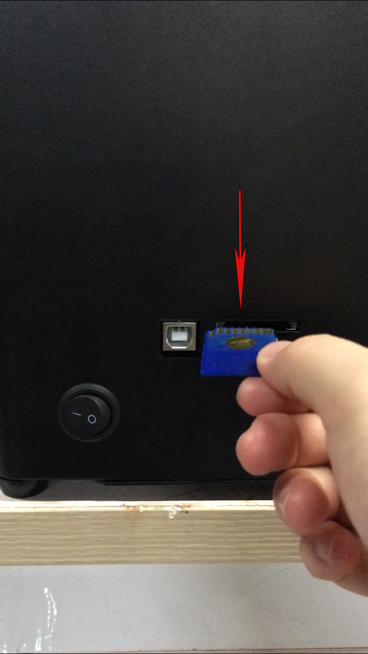
- Place the side with the chip facing upwards into the card slot and gently press inward. (Fig. P-38)
- When removing a memory card, first press the card inward and wait for it to pop out before removing it.
- Printing.
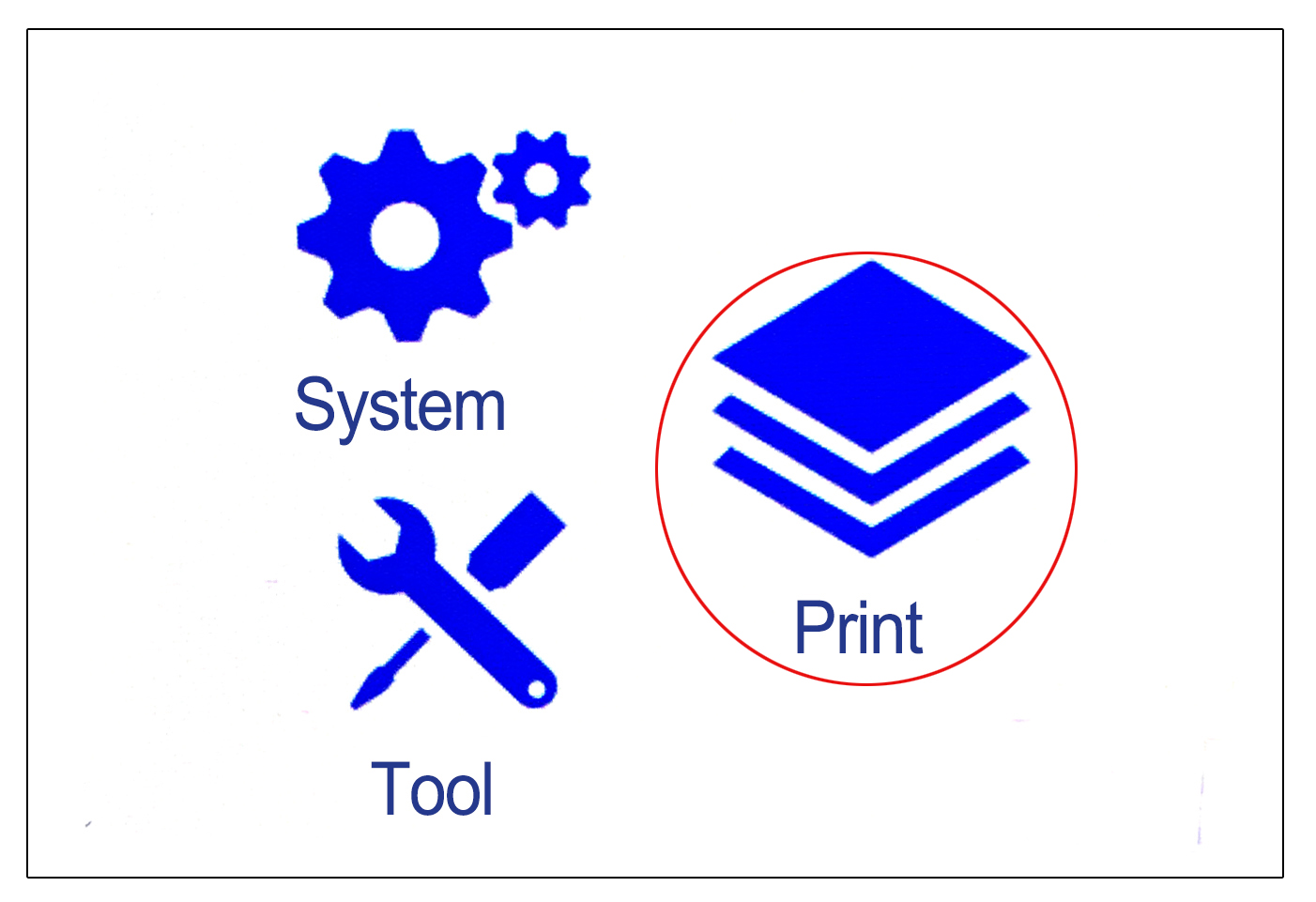
- Click on the [Print] icon in the control panel. (Fig. P-39)
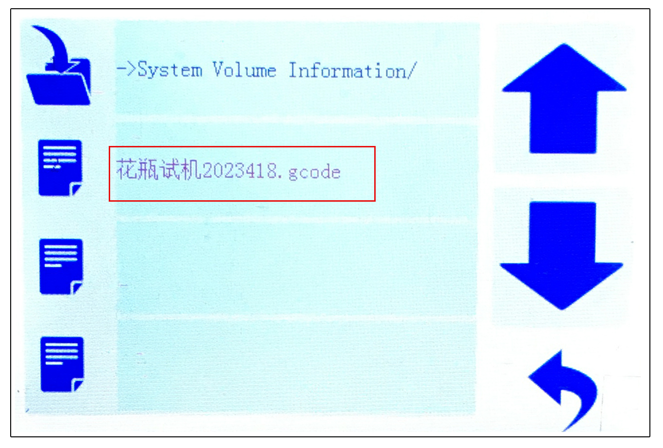
- Click on the model name that needs to be printed. (Fig. P-40)
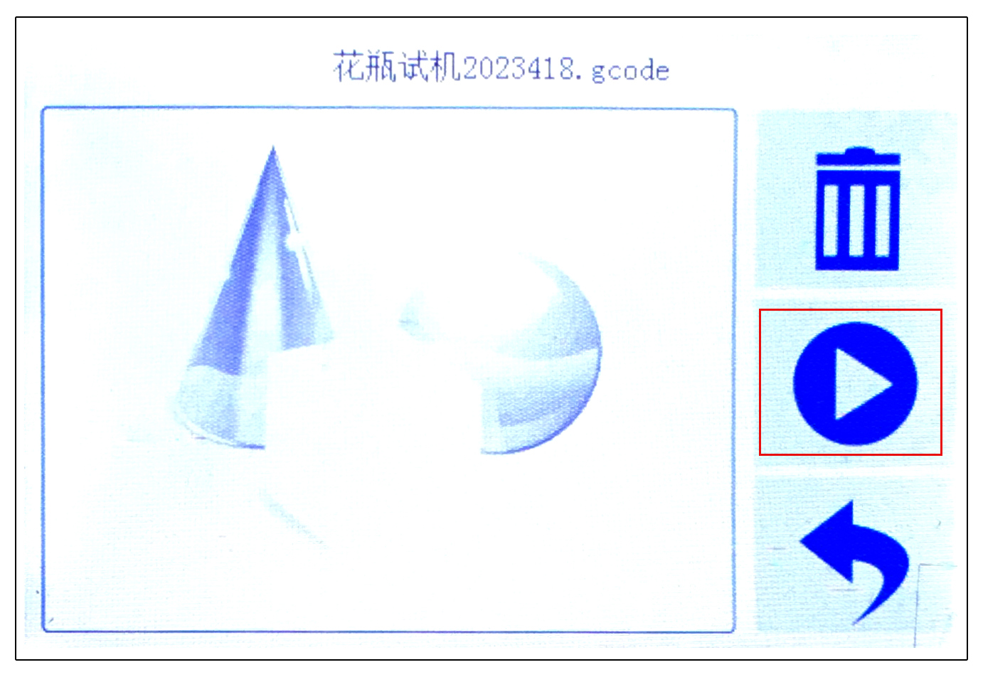
(There is a printed model in SD) - Click on the second [Start] icon on the right to start printing. (Fig.P-41)
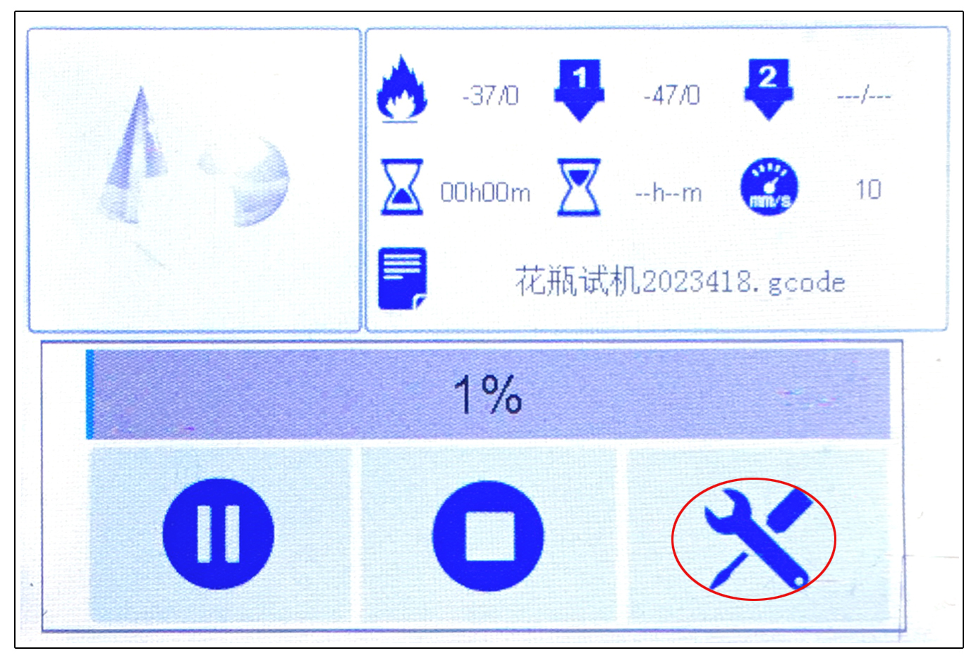
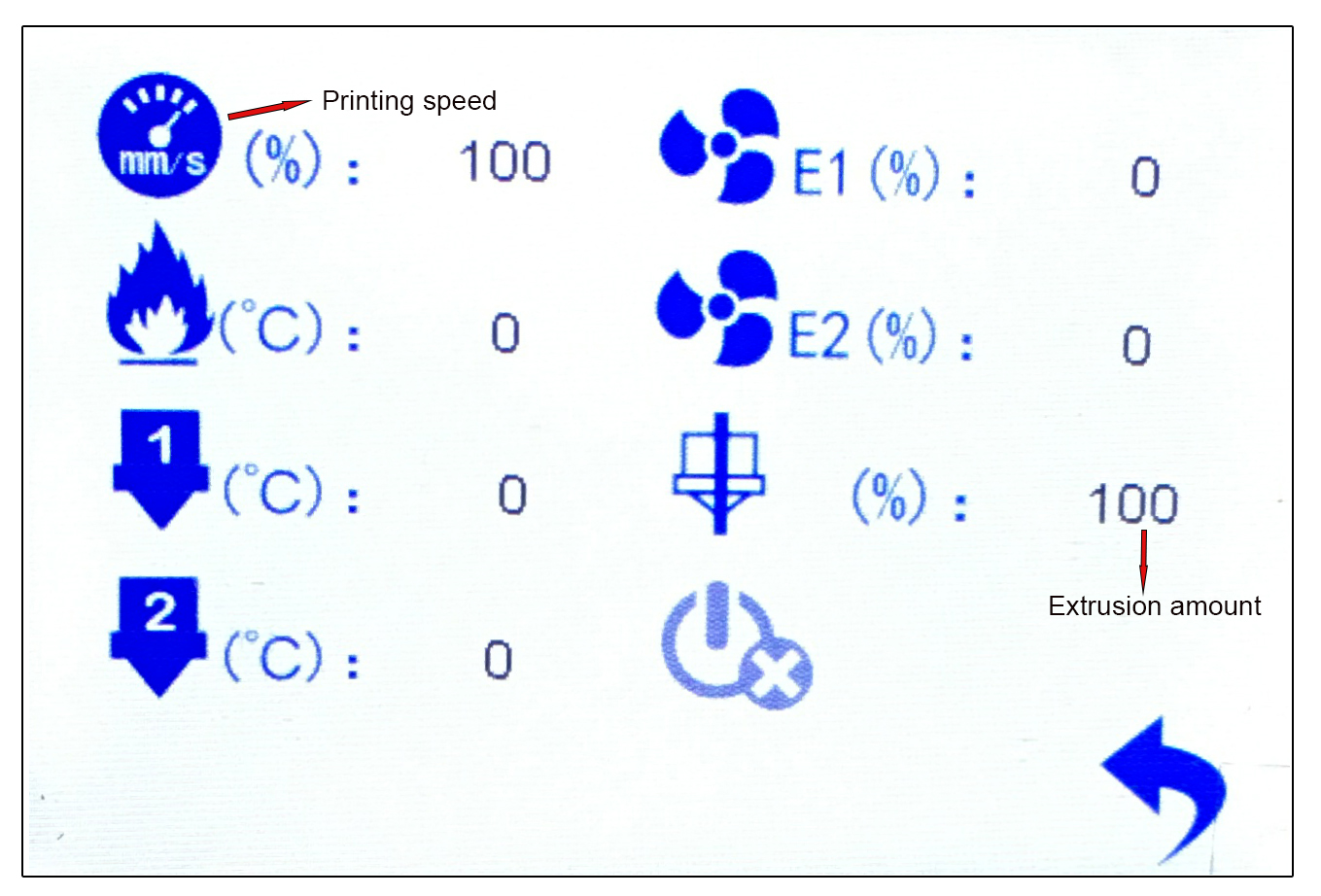
- You can adjust the printing parameters at any time by observing the printing situation. Click on the first [Settings] icon in the lower right corner of the control panel. (Fig.P-42)
- Adjust the amount of mud and printing speed according to the printing situation. (Fig. P-43)
· The printing speed of models with excessive hanging angles should not be too fast. - Installation of clay
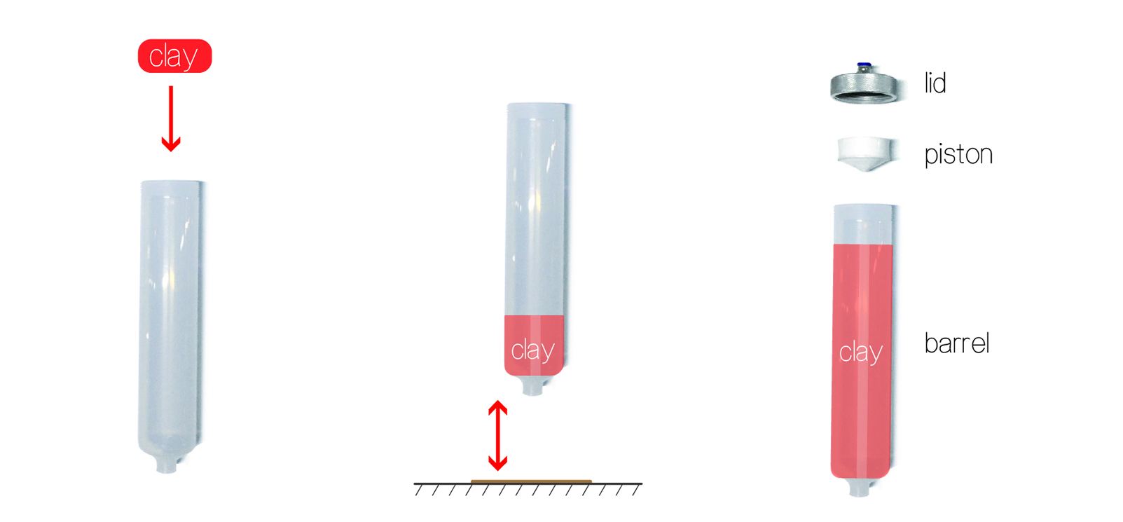
- Take small pieces of mud and put them into the material barrel. (Fig. P-44)
- On a flat floor or tabletop, tap the material barrel up and down to expel air, making the mud more compact and fitting better with the wall of the material barrel. (Fig. P-45)
- * The presence of bubbles in the mud can affect the printing effect and easily lead to uneven and non discharge of mud.
- Repeat the above steps to load the mud to about 80% of the barrel, insert the piston, and tighten the material cover. (Fig, P-47)
- * If the mud is not immediately used after being loaded, it can be stored in a water tank for moisture retention to prevent the mud from losing water and drying out.
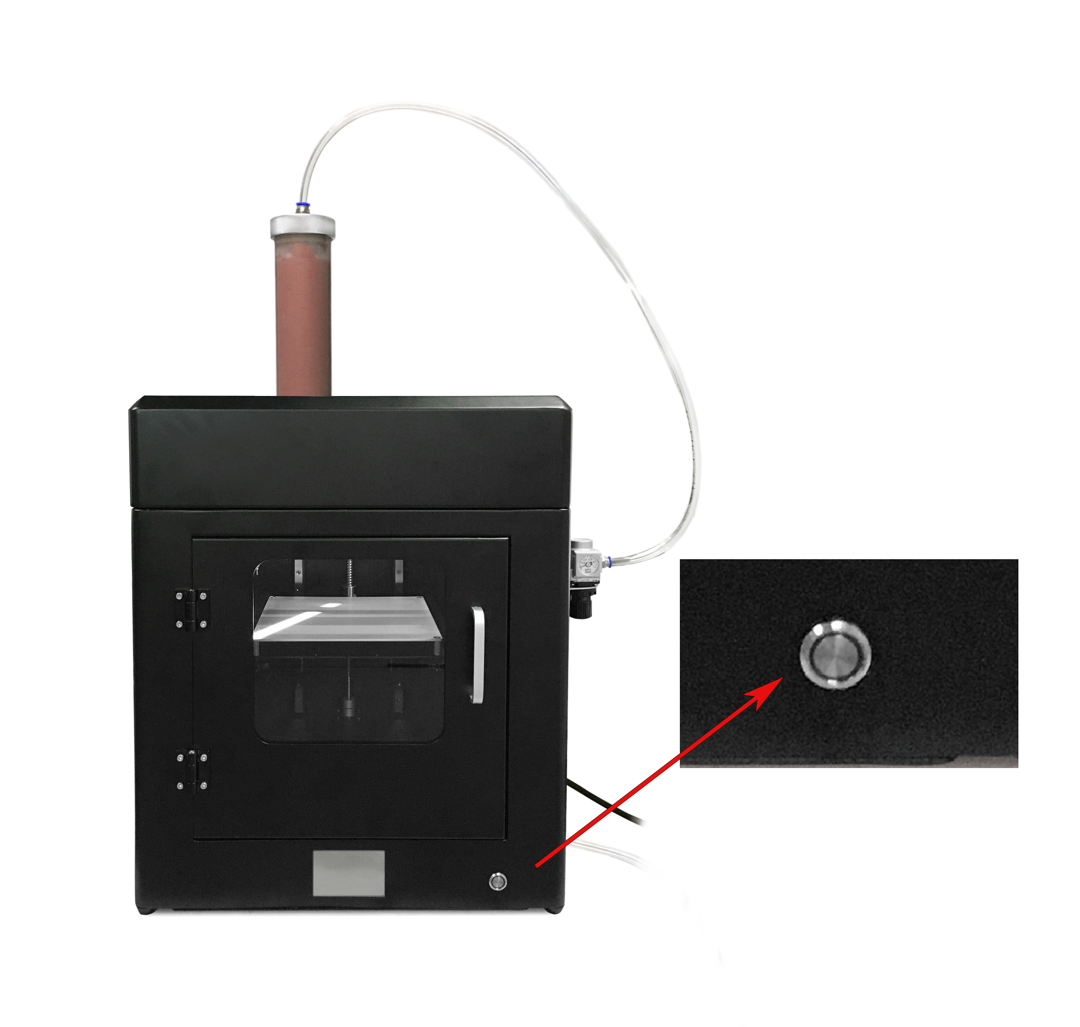
P-23
.jpg)
P-24
.jpg)
.jpg)
P-25
.jpg)
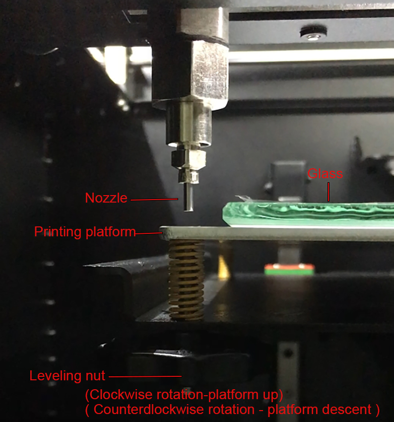
P-26
P-27
P-28
.jpg)
P-27
.jpg)
P-28
P-30
.jpg)
P-31
.jpg)
P-32
P-33
P-34
P-35
P-36
P-37
P-38
P-39
P-40
P-41
P-42
P-43
P-44 ,45,46
.jpg)
P-47
.jpg)