Replace Supplies
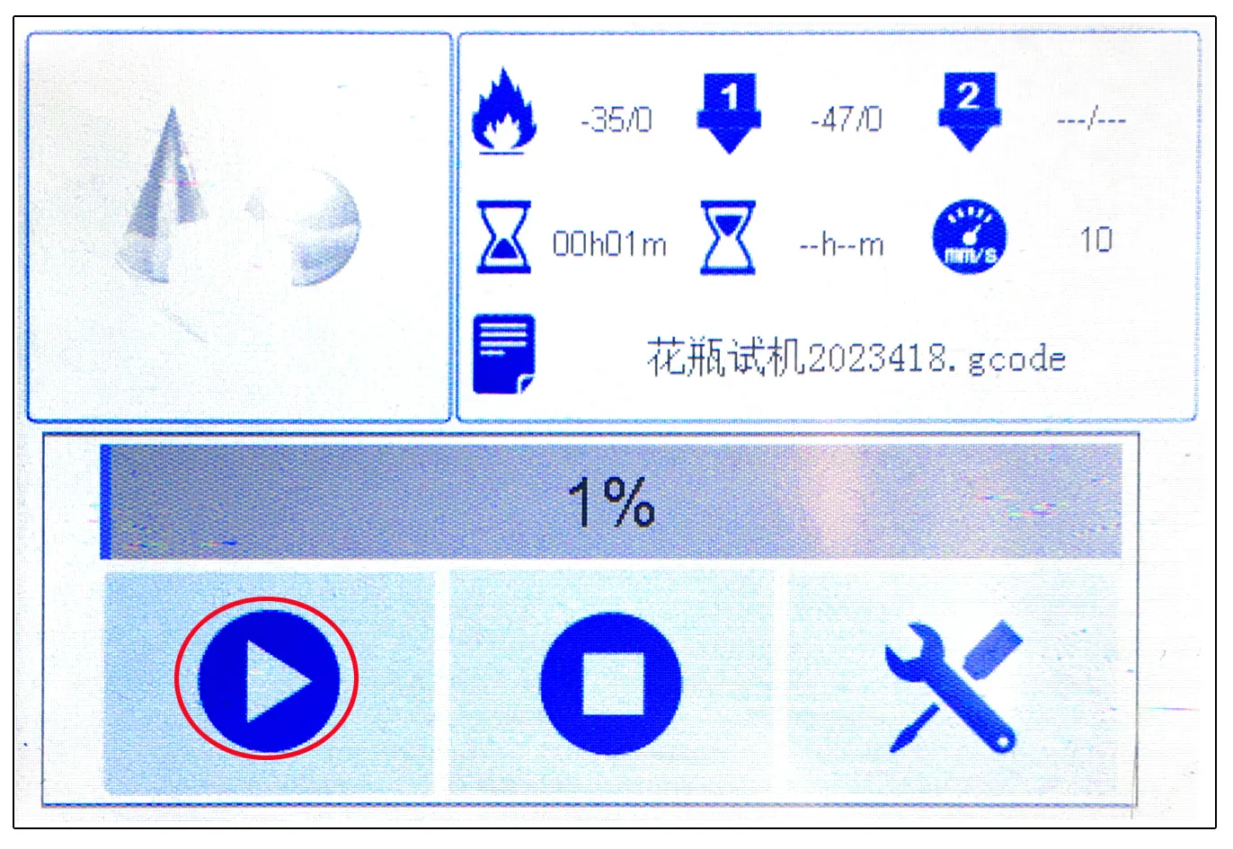
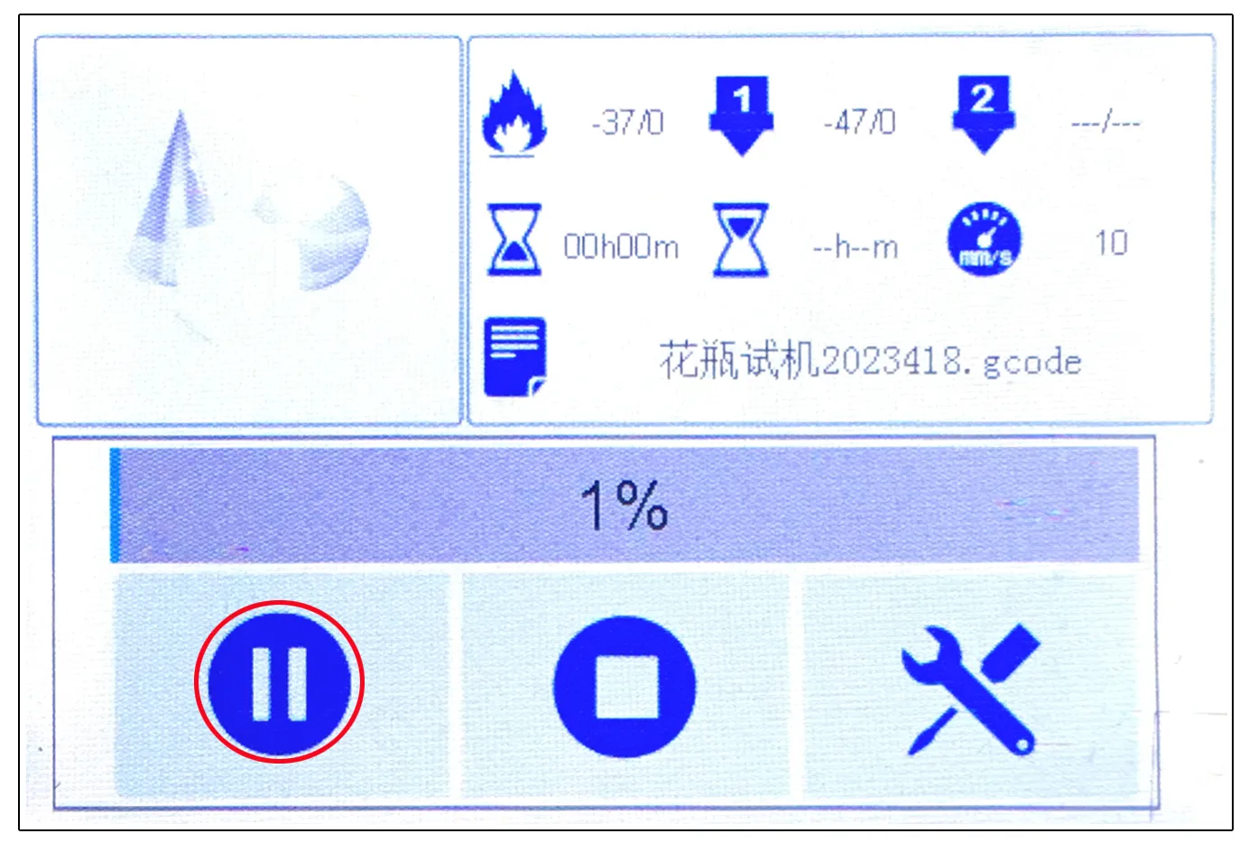
- 1. Click on the first [Pause] icon in the bottom left of the control panel. (Fig. P-41)
P-41
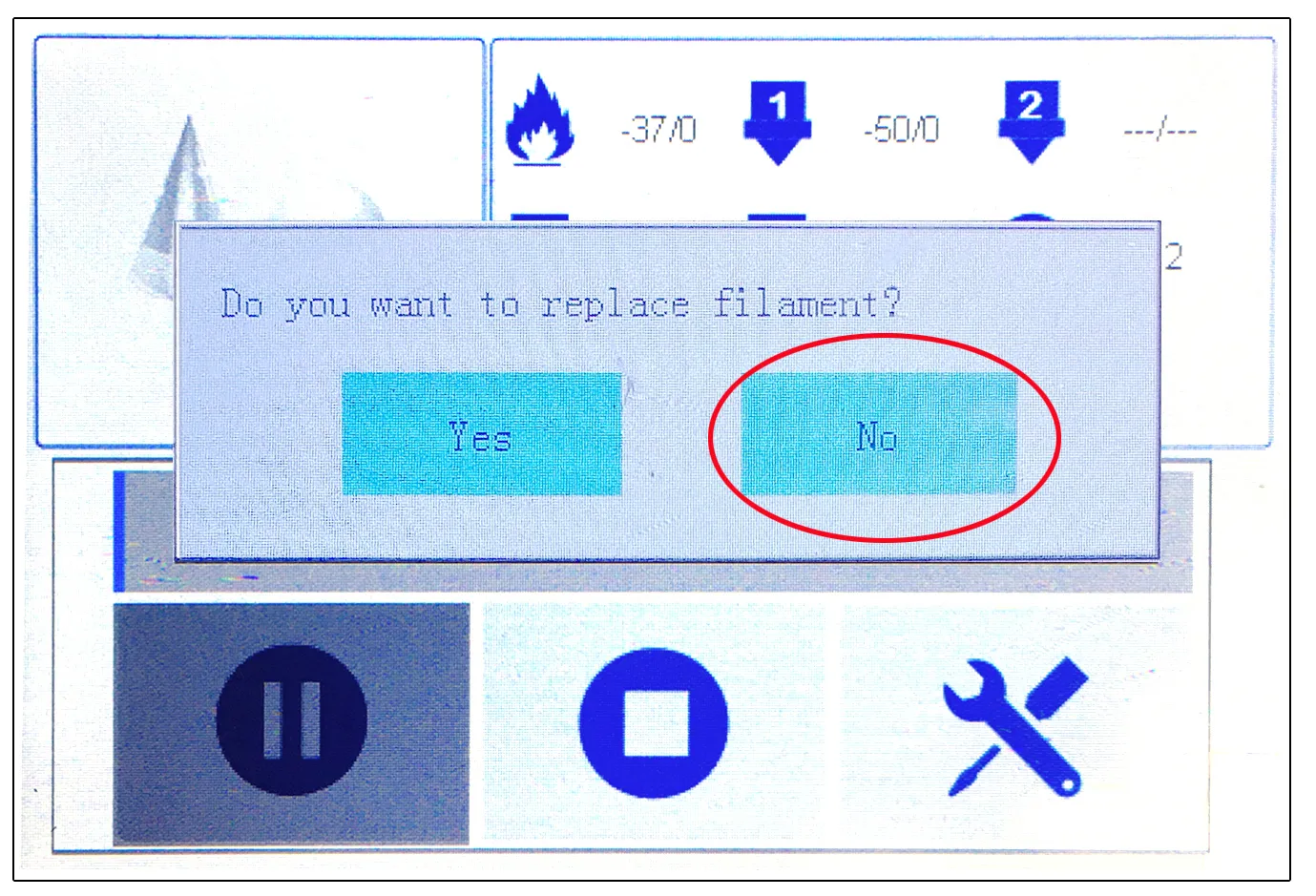
- 2. Click [No] in the new pop-up window. (Fig. P-42)
P-42
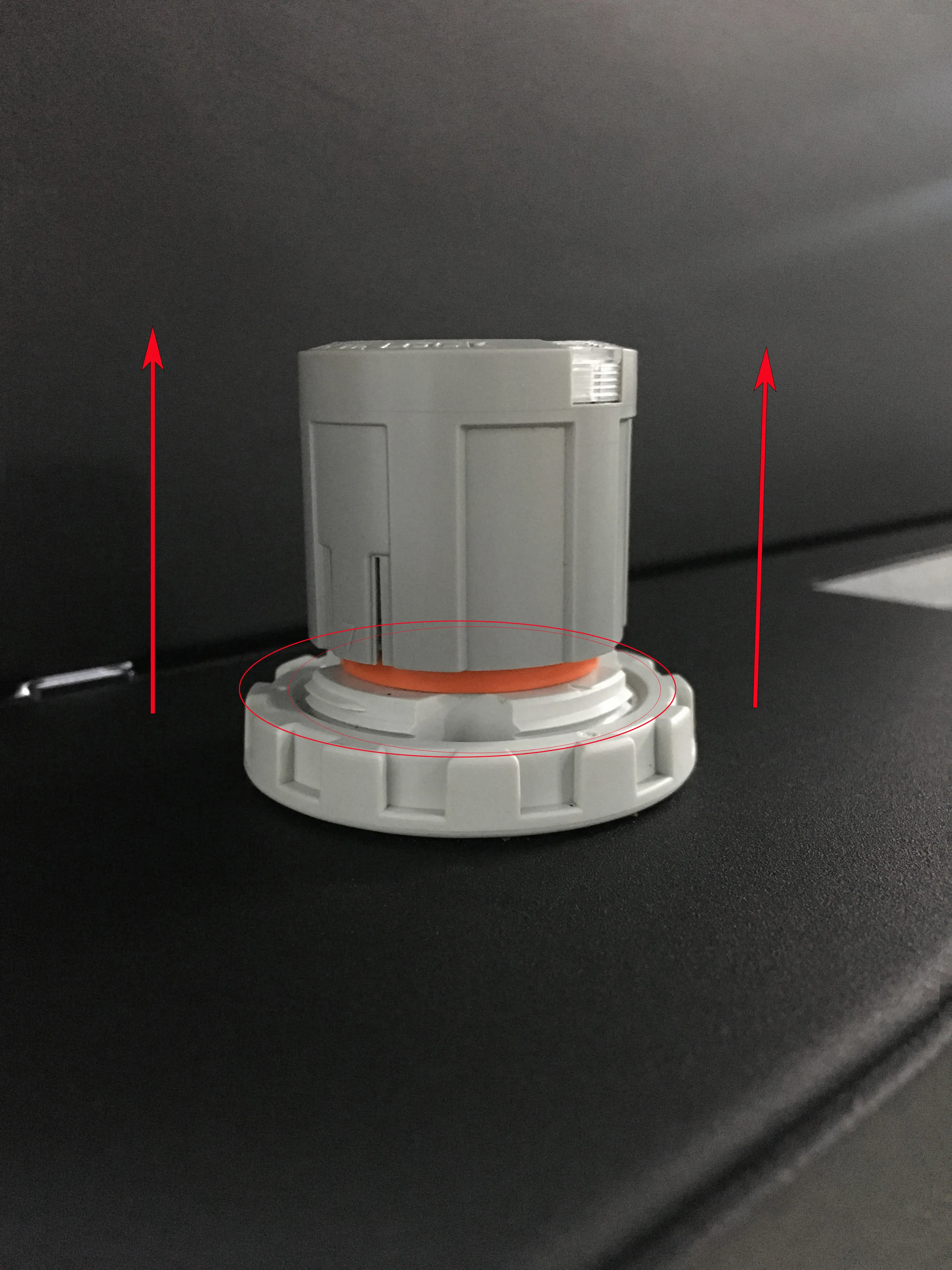
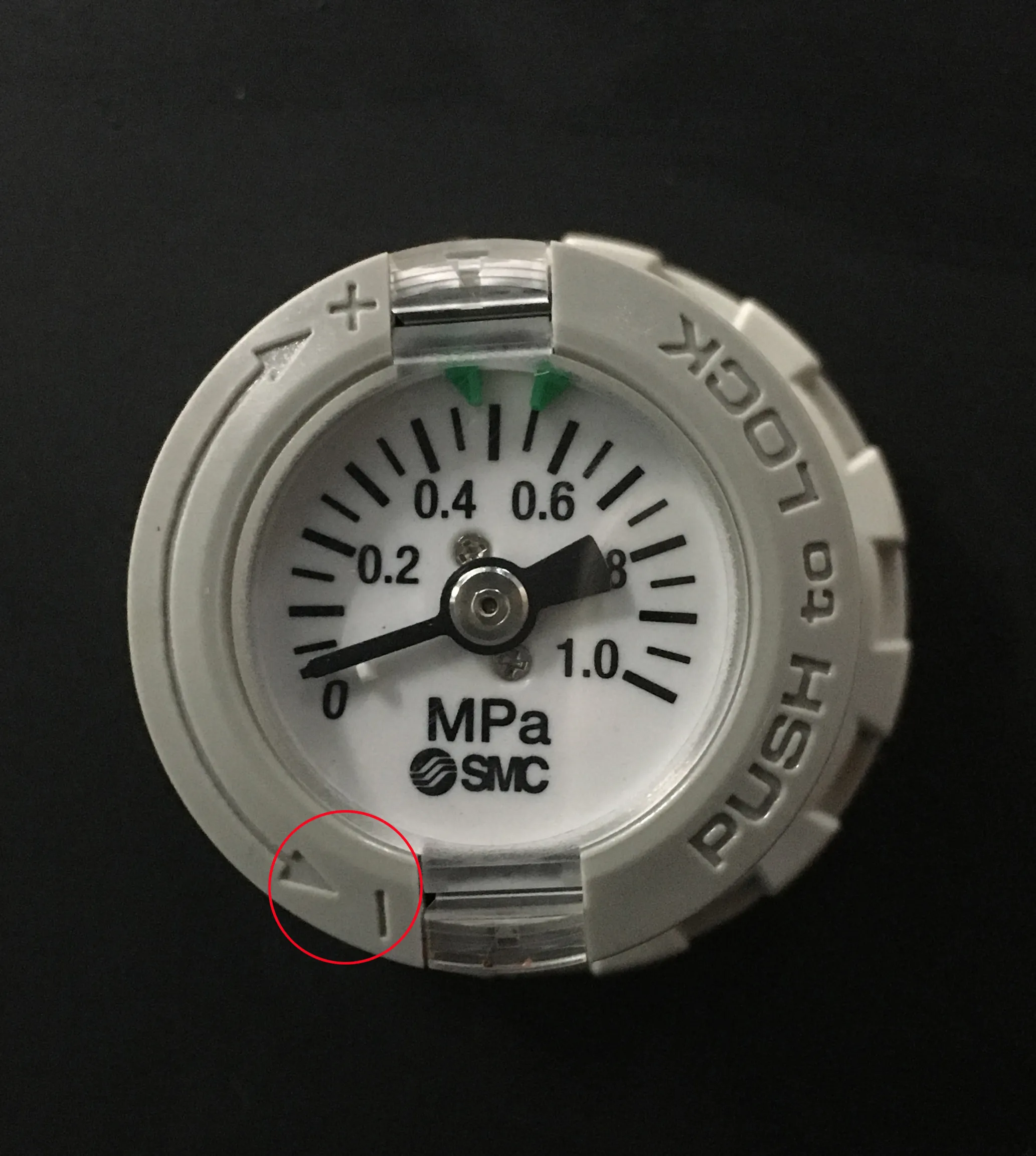
- 3. Pull up the pressure regulating valve knob, expose the orange part, and rotate according to the [- ] direction on the knob to release pressure to 0MPa. (Fig.P-43)
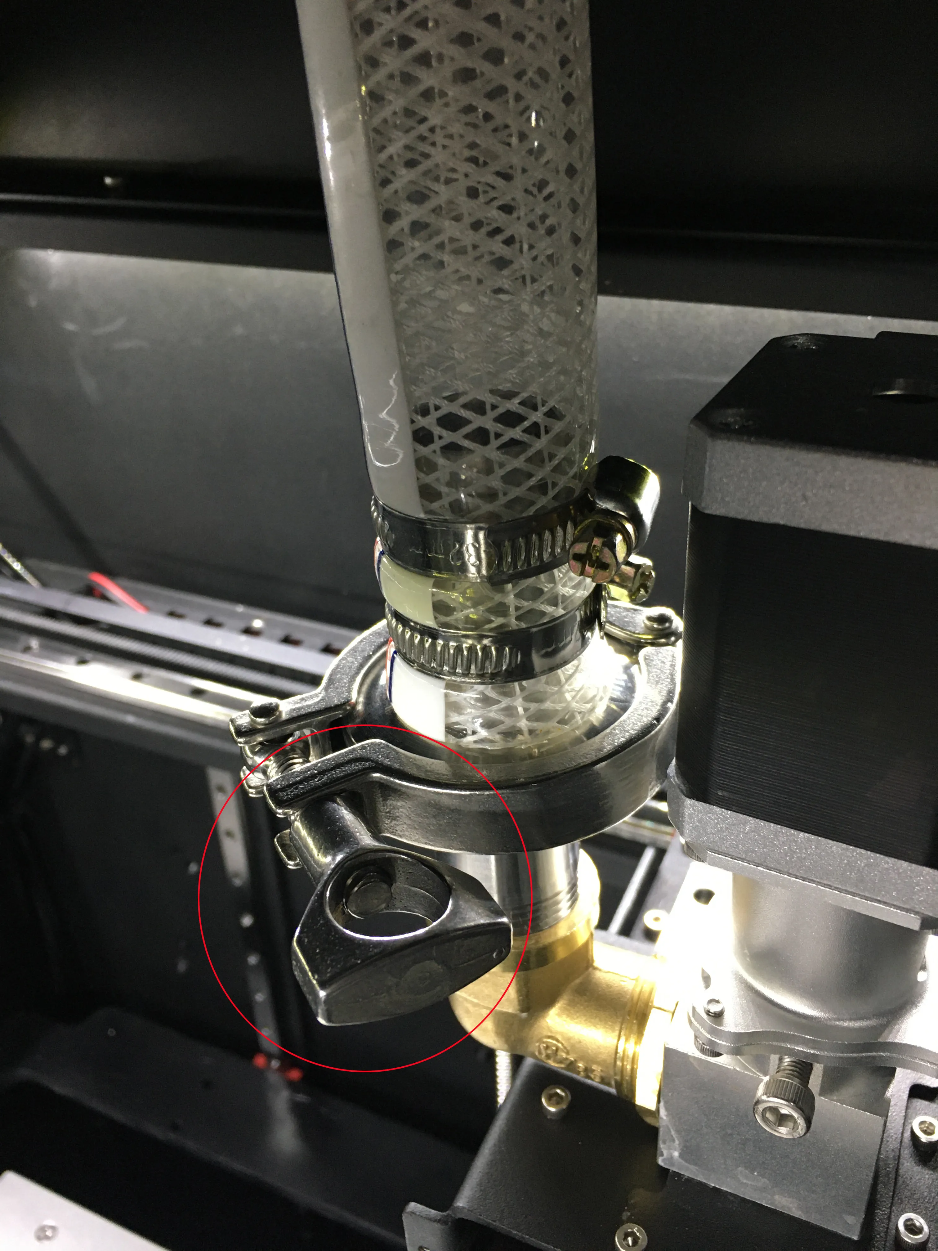
- 4. Remove the clamp connecting the feed pipe and the extruder feed port. (Fig. P-44)
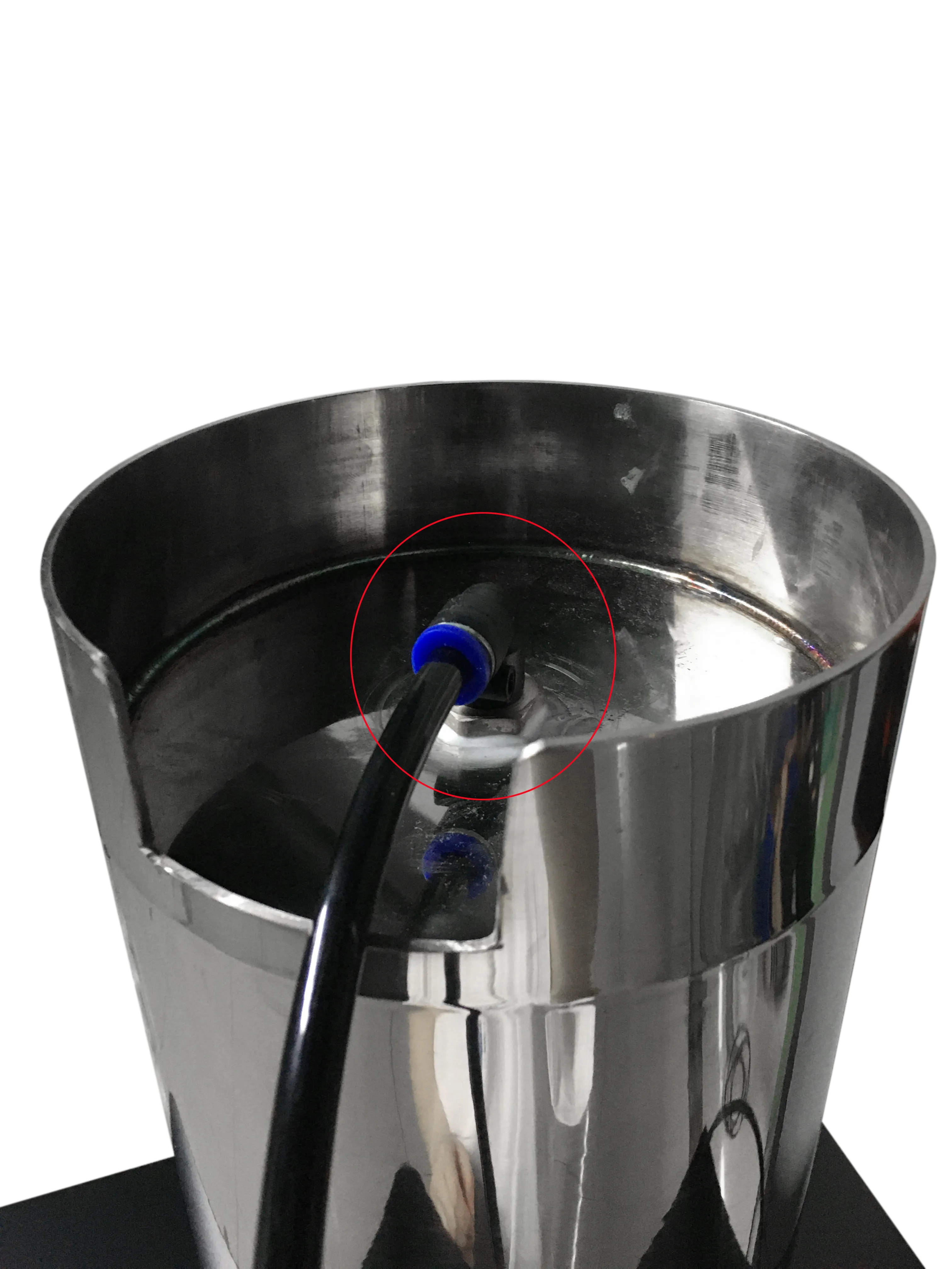
Remove the intake pipe above the tank. (Fig. P-45)
P-44
P-44
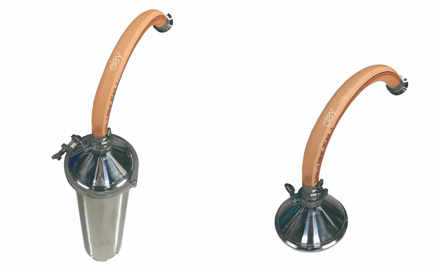
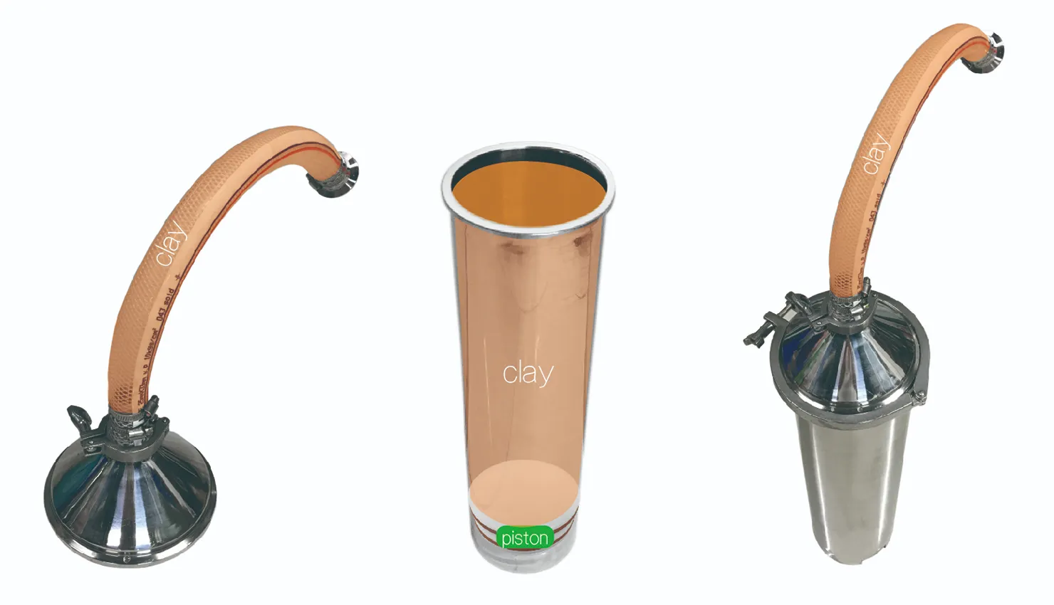
- 5. Remove the material tank together with the feed pipe. (Fig.P-46)
Remove the material cover (do not remove the feed pipe) (Fig. P-47)
P-46 & P-47
- 6. Replace consumables.
- ① Install the removed material cover (including the feed pipe) directly onto the clay filled tank, place a gasket, and then lock it with a clamp. (Fig. P-48)
- ② Fill the raw material tank with clay for use.
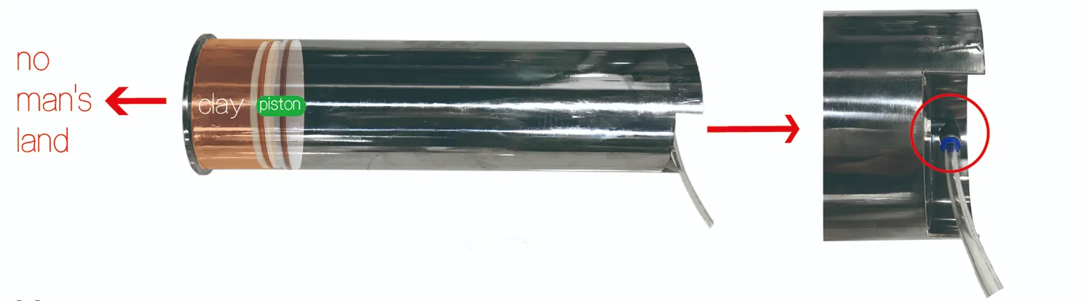
- a、 Place the material tank flat on the ground, insert a gas pipe (Fig. P-49) at the inlet end of the tank, slowly pressurize and inflate the tank, and discharge the remaining clay and piston. Due to the pressure difference between the inside and outside, there will be a "bang" sound when the piston is discharged, which is a normal situation;
- *When operating, face the discharge port of the material tank towards the direction of no one to prevent the discharged material from being sprayed and injured due to excessive pressure.
- b、 After discharging the remaining clay and piston, please refer to the clay loading method on page 7 and reinstall the clay.
P-48
P-49
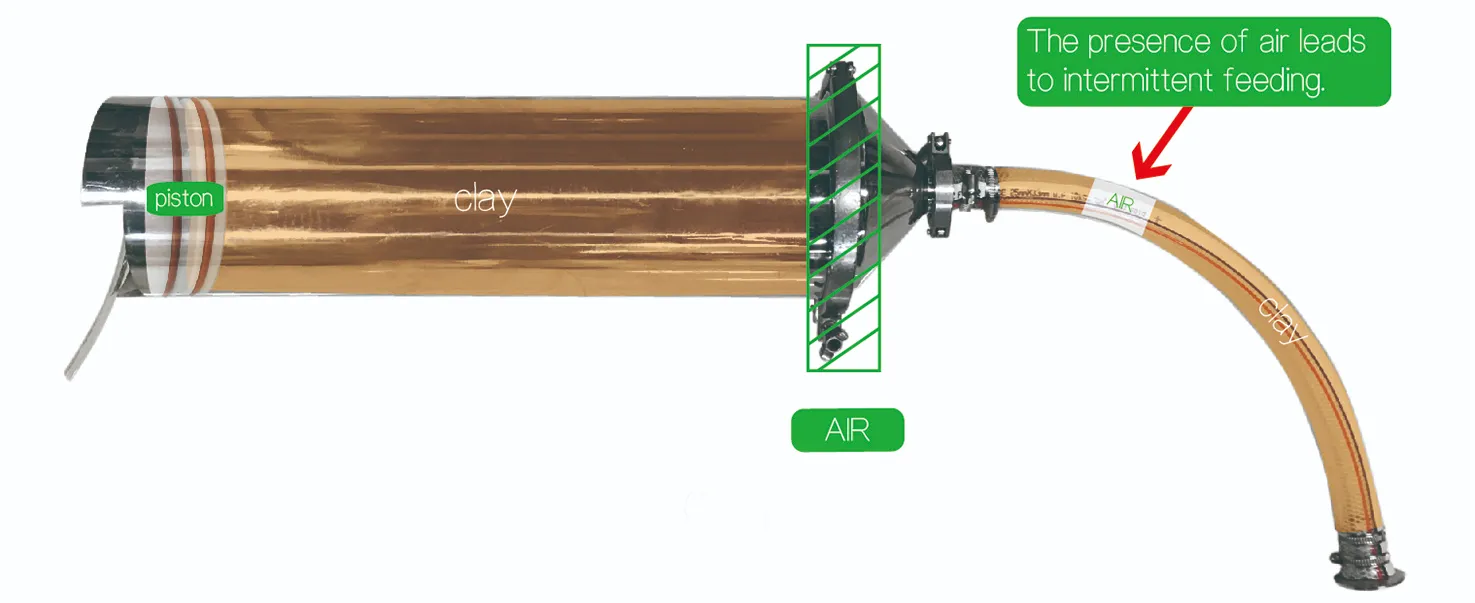
- 7. To prevent internal residual air from causing material interruption during the printing process, after the assembly of the material barrel is completed, insert a gas pipe and discharge a section of mud until the mud in the feeding pipe is not interrupted (Fig. P-50)
- 8. Then put the material barrel back into the material rack, and connect the other end of the material pipe to the feeding port of the extruder. Before connecting, you can manually fill some mud (Fig. P-51) to make the mud at both ends of the interface denser and reduce air. Lock the interface with the clamp. (Fig P-52)
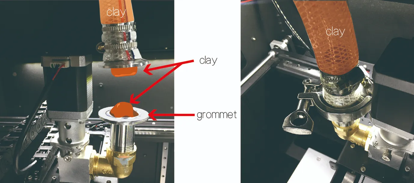
P-51 & P-52
- 9. Finally, connect the gas pipe to the feeding bucket, increase the pressure through the pressure regulating valve, and click on the first [Start] icon in the control panel to continue printing from the previously paused location. (Fig. P-53)